To make a good solid we need to develop combination of
surfaces with good quality by its terms, surfaces has many type
of quality. as I learned when work with Rhino the most important
is a surface must have good continuity. Visually, Continuity is
a flowing line direction above surface to make it easy to understand
lets try to do some practice.
On this opportunity we practice to make this 3D logo.
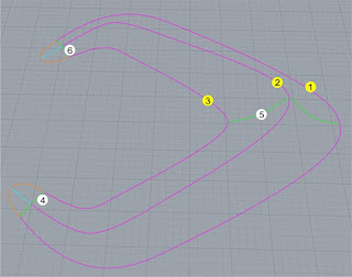
To make solid 3D logo we need to build basic surfaces over construction lines. First download this construction line sample : shape sample.3dm As I known these methods are technically suitable to be used.
A. Surface from Curve network (one surface)
Step 1
Do command NetworkSrf (menu: Surface>Curve Network). on this first step option we just need to create one surface part for entire logo.
Step 2
Select all line curves then enter then we get the result.
Let's check the flow :
Environment Map :
Select surface and do command _Emap
(menu: Analize>Surface>Environment Map).
Let's check the flow :
Zebra :
Select surface and do command _Zebra
(menu: Analize>Surface>Zebra).
 |
| Full Networksrf |
From Zebra analyzation the result is it has flow continuity of course because it is built just by one surface.
B. Surface from curve network (Two surfaces)
Step 1
On this second step option we create logo built by two surfaces. Do command NetworkSrf (menu: Surface>Curve Network) and activate NoAutoShort.
Step 2
Select all curves (Magenta) for first direction then for second direction select all curves (Green) then Enter.
Step 3
Select curves (Green) for first direction then for second direction select all curves (Orange and Cyan) and Enter.
Let's check the flow :
Environment Map :
Select all surfaces and do command _Emap
(menu: Analize>Surface>Environment Map).
 |
| Group of Two NetworkSrf |
Let's check the flow :
Zebra :
Select surface and do command _Zebra
(menu: Analize>Surface>Zebra).
 |
| Group of Two NetworkSrf |
From Zebra analyzation it has discontinuity of flow at intersection between two surfaces.
It can be fixed by merge the two surfaces so it will have flow continuity.
C. Surface from Sweep 2 Rails (Six surfaces)
Step 1
On third step option we create surface built by six parts.
Do command Sweep2 (menu: Surface>Sweep 2 Rails)
Select first curve (Orange) for first rail then select curve (Cyan)
for second rail, finally select all curves (Green) as Cross section
curves then Enter.
Step 2
Do command Sweep2 (menu: Surface>Sweep 2 Rails) Select first curve (Magenta) for first rail then select curve (Cyan) for second rail, finally select all curves (Green) as Cross section curves then Enter.
Step 3
Do command Sweep2 (menu: Surface>Sweep 2 Rails) Select first curve (Magenta) for first rail then select curve (Cyan) for second rail, finally select curve (Green) as Cross section curves then Enter.
Step 4
Do command Sweep2 (menu: Surface>Sweep 2 Rails)
Select first curve (Cyan) for first rail then select curve (Orange)
for second rail, finally select curve (Green) as Cross section
curves then Enter.
And do same action command Sweep 2 Rails for the remnant
curves.
Let's check the flow :
Environment Map :
(menu: Analize>Surface>Environment Map).
 |
| Group of Six Sweep2 |
Let's check the flow :
Zebra :
(menu: Analize>Surface>Zebra).
 |
| Group of Six Sweep2 |
CONCLUSION
As we can see from top view the visual comparison between three option methods of surfacing. Clearly that logo by method option A has good flow continuity but it has lack of surface consistency because surface flows exceed the ground plane (Red area). Option B has discontinuity of flow at meet point edge between surfaces.
Option C method that consist from six surfaces is more accurate because its surface directions are created as expected, there are no surface parts looks drown. Clearly they did’nt crossed the ground plane.


0 Komentar