To align objects in AutoCAD we need to determine the source point
and the destination point. The source point determined by first object and the destination point determined by second object.
Lets make our first basic object for rectangle and triangle , here this is
the following command lines are:
➤ Make rectangle with length : 25 cm and width : 25 cm :
Command: RECTANG
Specify first corner point or [Chamfer/Elevation/Fillet/Thickness/Width]: Click on modelspace
Specify other corner point or [Area/Dimensions/Rotation]: @25,25
➤ Make polygon formed by 3 sides with radius 15 cm :
Command: POL
POLYGON Enter number of sides <4>:3
Specify center of polygon or [Edge]: Click on modelspace
Enter an option [Inscribed in circle/Circumscribed about circle] <I>: I
Specify radius of circle: @15<180
This is example that we want to align the OBJECT A to OBJECT B, so here OBJECT A as our first object and OBJECT B as second object.
Step 1
Do command ALIGN
Step 2
Select object: select OBJECT A and Enter.
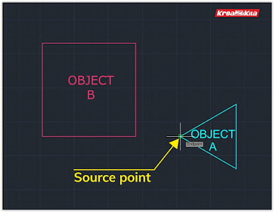
Specify first source point: take point at Endpoint of OBJECT A and Enter.
Step 3
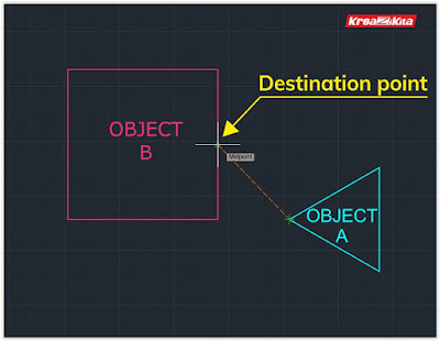
Specify first destination point: take point at Midpoint of OBJECT B and Enter.
 |
| The Result |
Or we can take different destination point :
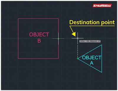
Specify first destination point: take point at intersection track line between Endpoint of OBJECT A and Midpoint of OBJECT B and Enter.
 |
| The Result |
➥ How about ALIGN for scaling ?
 |
| Starting position |
Now back to the earlier object position and we make ALIGN command once again to go to this scaling phase that will executed after the second destination point is specified, when the command line order us to specify third source point we have to leave it blank or we just hit Enter button. So we will taken to scaling option that will transform source object’s dimension into destination object’s dimension based on points we have specified.
 |
| Point Selection |
Here the input sequence on command line AutoCAD :
Command: 2DALIGN
Select objects:Select Polygon 3 sides object
Specify first source point: Point no. 1
Specify first destination point: point no. 2
Specify second source point: point no. 3
Specify second destination point: point no. 4
Specify third source point or [Continue]<C>: pass this command
line just hit ENTER
Scale objects based on alignment
points? [Yes/No]<N>: Y (select Yes for object scaling)
From ALIGN command we can align many objects simultaneously from group of objects, all we need is just the source point and its destination point. Source point behave as main reference or hand-grip meanwhile destination point occurred as target point.
➥ How about ALIGN for 3D Objects ?
In the above example, ALIGN command was applied to 2D objects
then how about implementation of ALIGN command for 3D objects.
Basically about object aligning there are similarity between 2D with 3D,
the different only at its command flow sequences.
On 2DALIGN command, the source point and destination point
are specified simultaneously, the first step is to specify first source
point together with its destination point then the second step is
to specify second source point with its destination point and so forth
depending on your need.
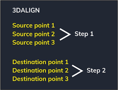
On 3DALIGN the source point and destination point are specified consecutively, first step is only to specify source point entirely then second step is only to specify destination point entirely.
Now lets create 3D object from existed 2D objects rectangle and triangle, we just need to pull from their bounded area :
- Type command PRESSPULL make selection to bounded area on rectangle then type 20 cm.
- Type command PRESSPULL make selection to bounded area on triangle then type 15 cm.
Here this stage after we have made the 3D objects lets try 3DALIGN
command, our purpose is to align the triangle to rectangle it is mean the
source point is on triangle meanwhile the destination point is on
rectangle.
Specify the source point : point no. 1 and point no. 2, destination point :
point no. 3 and point no. 4.
 |
| Point Selection |
Here the input sequence on command line AutoCAD :
Command: 3DALIGN
Select objects: select triangle then ENTER
Specify source plane and orientation ...
Specify base point or [Copy]: point no. 1
Specify second point or [Continue]<C>: point no. 2
Specify third point or [Continue]<C>: type C or ENTER
Specify source plane and orientation ...
Specify first destination point: point no. 3
Specify first destination point: point no. 4
Specify second destination point or [eXit]<X>: type X or
just hit ENTER
And here the result from 3DALIGN command.
 |
| The result |
The option for rotation addition can be added to align operation when we continue to last command line that is to specify third destination point :
And this is the next result from 3DALIGN command with rotation addition option.
 |
| The result with rotation |
Command: 3DALIGN
Select objects: select triangle then ENTER
Specify source plane and orientation ...
Specify base point or [Copy]: point no. 1
Specify second point or [Continue]<C>: point no. 2
Specify third point or [Continue]<C>: type C or ENTER
Specify source plane and orientation ...
Specify first destination point: point no. 3
Specify first destination point: point no. 4
with rotation addition option :
Specify third destination point or [eXit]<X>: point no. 5
just advice : on align command it is very useful to activate OSNAP because it will help user when dealing with point selection command among objects. And it is necessary to activate ORTHOMODE that helpful when user specify the next destination point that make rotation and tilt to the source object, because rotation degree selections are available automatically. And with 3D solid models, it is recommended that you turn on dynamic UCS to speed the selection of the destination plane.


0 Komentar